

LINESIDE DETAILING
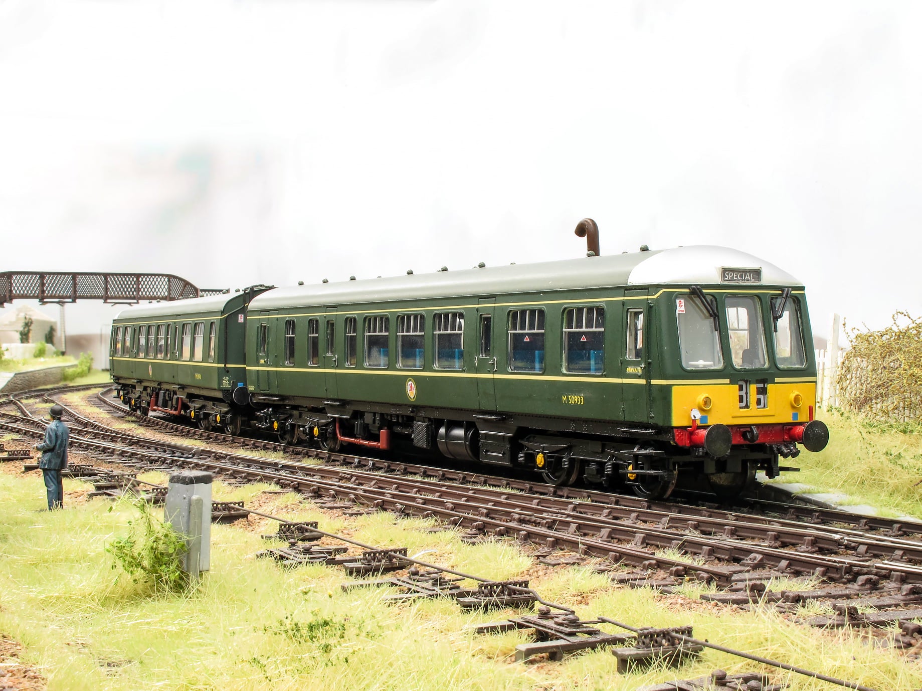
The railway’s lineside infrastructure was essential to keeping trains moving safely, yet much of it is easily overlooked when modelling a scene. Point rodding, signal wires, cranks, compensators, connected signal boxes with points and signals across the railway.
This guide looks at the equipment found beside the track, how the different components worked together, and the staff responsible for installing, inspecting and maintaining them. Adding even a few carefully placed details can bring realism and purpose to an otherwise empty stretch of lineside.
SIGNAL BOX LEAD OFF BOARD
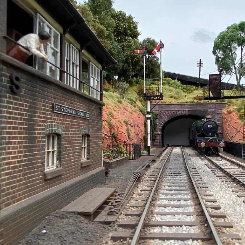
The leadoff board carried the first series of cranks and pulleys outside the signal box, directing point rodding and signal wires towards the equipment they controlled. It forms the starting point of the mechanical signalling system.
Image courtesy of Stephen Fay

2150 Signal Wire Pulley Wheels x20

2128 BR High Accommodating Cranks x5


RODS AND ROLLERS
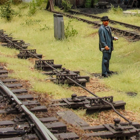
Point rodding rollers supported long runs of metal rodding between the signal box and the points. Mounted at regular intervals on small stools or frames, they kept the rods aligned and allowed them to move freely when a lever was operated. Each company had their own design, many of which can still be seen on mechanically operated sections of the present day railway network.
Image courtesy of Dan Evason


2102 BR / LMS Point Rodding Stools


COMPENSATORS
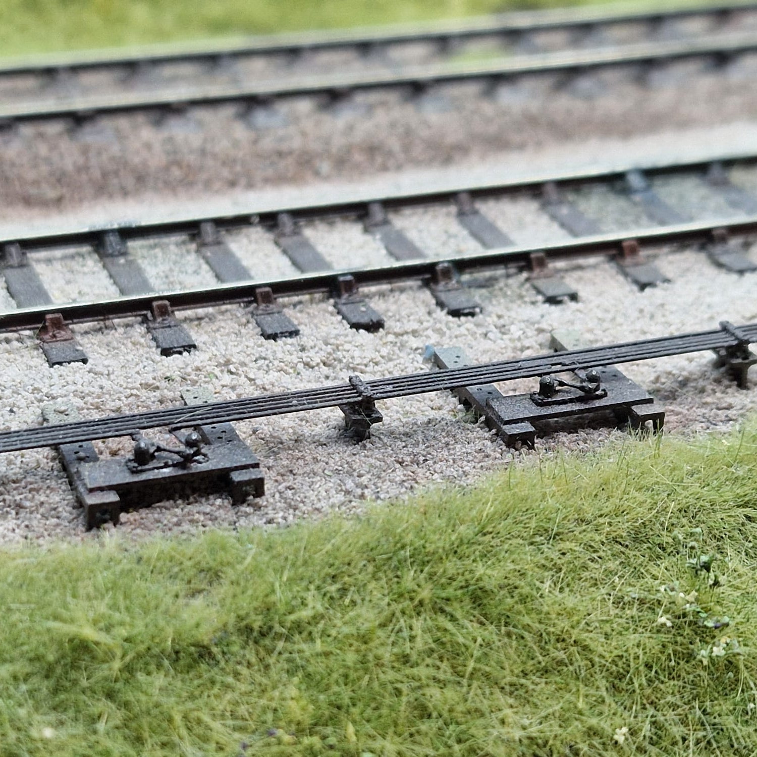
Compensators helped counteract the expansion and contraction of long rodding runs caused by changes in temperature. Without them, seasonal movement could affect the position of the points or make the signal box lever increasingly difficult to operate.


CRANKS
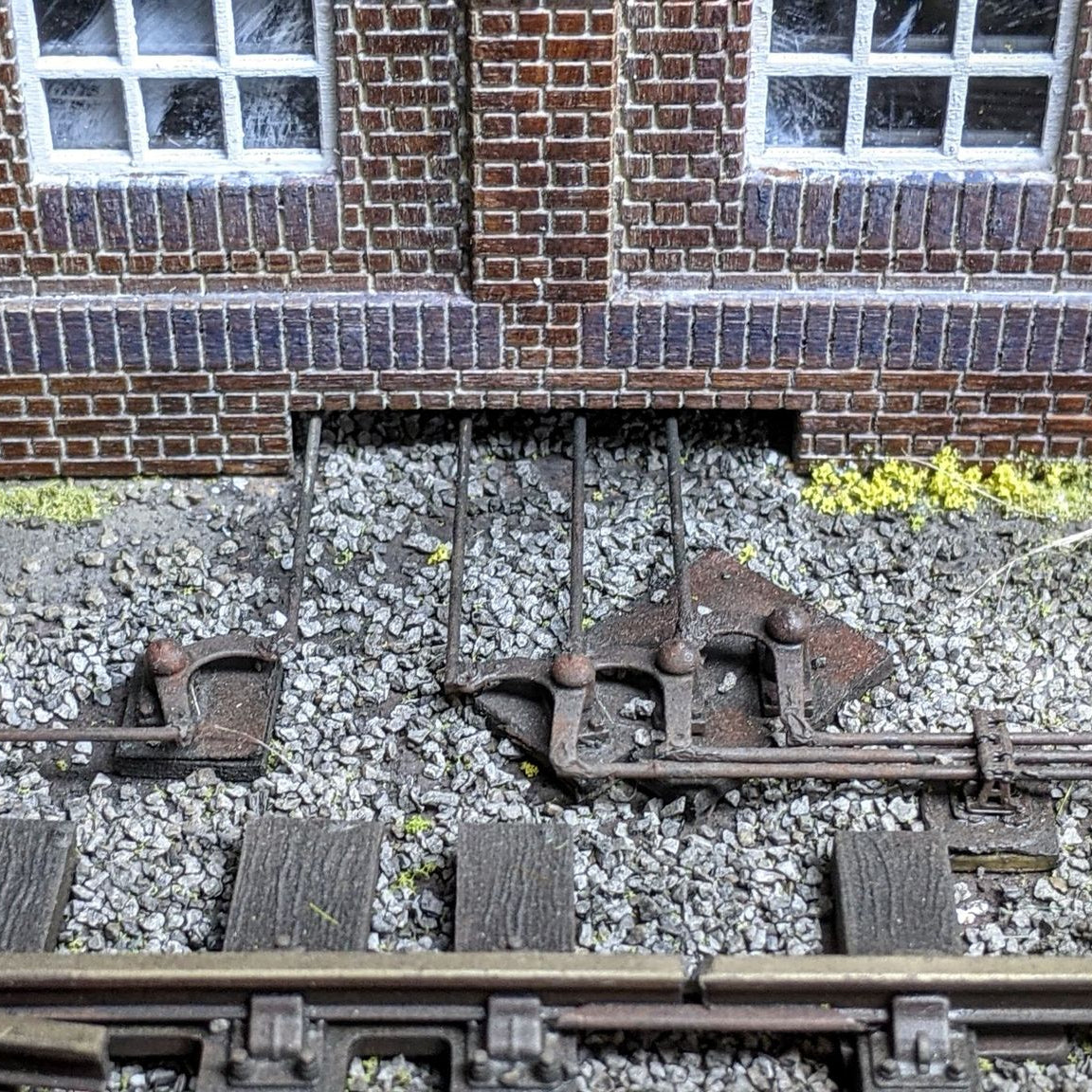
Cranks were used to change the direction of point rodding and transfer movement around obstacles, corners or changes in alignment. They appeared in a variety of sizes and arrangements depending on the space available and the equipment being operated.
Image courtesy of Dan Evason


2114 GWR Cranks x6 (Medium base)

FACING POINT LOCKS
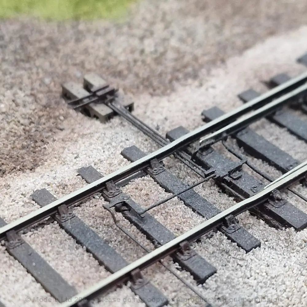
Facing point locks provided an additional safeguard where trains approached the points from the direction in which the route divided. The mechanism physically locked the point blades in position, preventing movement beneath a passing train.


2130 BR Mk1 FPL Point Kit (Pre-1973)


MANUAL POINT OPERATION
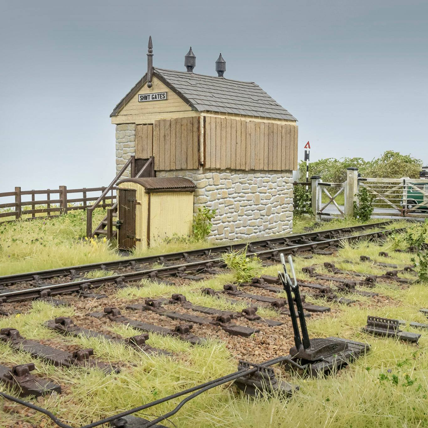
Not every set of points was controlled from a signal box. Sidings, yards and lightly used connections were often operated manually using point levers, or ground frames.
Image courtesy of John Chivers


CASES and CABINETS
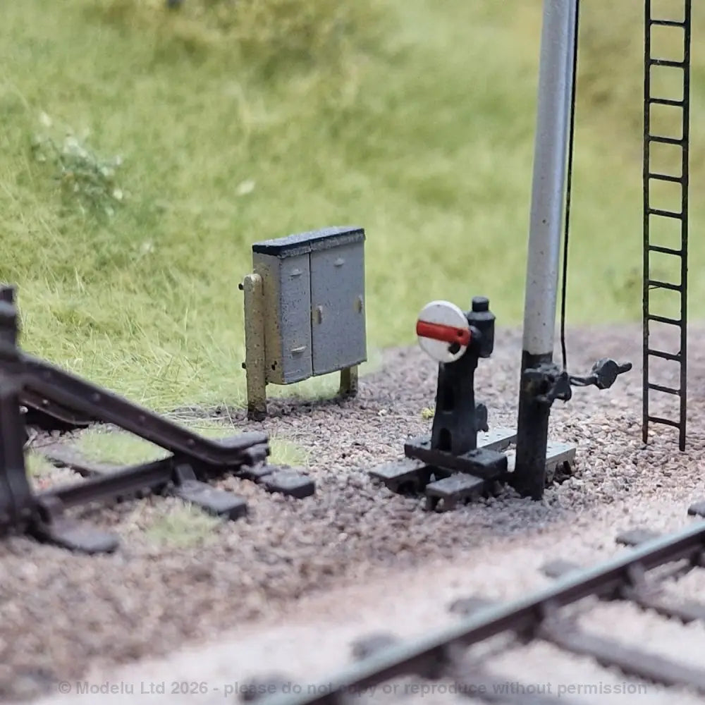
Lineside cabinets and equipment cases protected electrical, signalling and telecommunications equipment from the weather. Their appearance varied considerably by railway company, period and purpose, from small timber boxes to larger metal location cabinets.

2164 WR 1980s Tall Lineside Cabinets x5


2162 Medium Lineside Cabinets x5

2165 Modern Lineside Cabinets x5
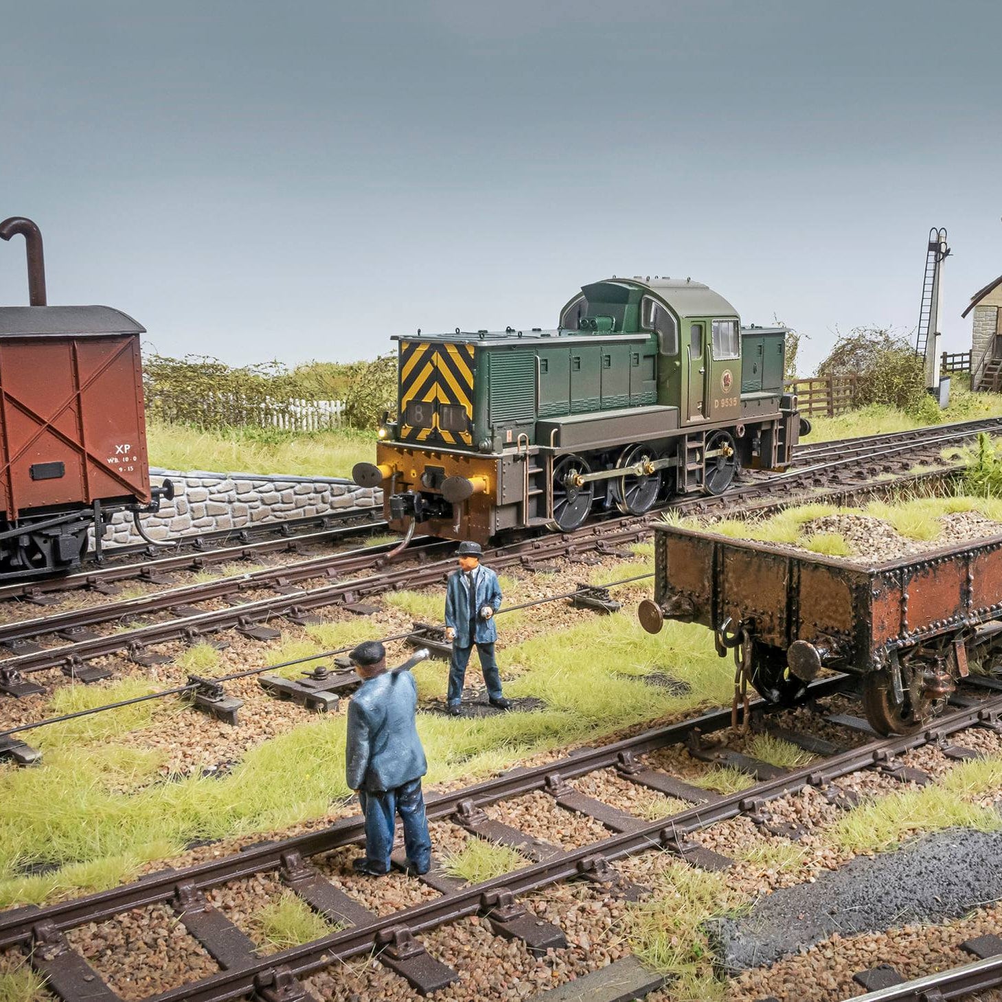
PERMANENT WAY and S&T ENGINEERS
Permanent way gangs maintained the track, sleepers, ballast and drainage, while signalling and telecommunications engineers looked after the equipment controlling the railway. Both groups were a familiar lineside presence, carrying tools, inspecting equipment and working around live railway operations.
Image courtesy of John Chivers

11180 Wickham Trolley Crew Pack


Rodding Reference
Images of point rodding, detectors, cranks, facing point locks and compensators taken with permission outside Bridgnorth Station.


SHOW US YOUR POINT RODDING
We’ve shown you our scenes, now it’s your turn!
Share your photos with us on social media using #Modelu for a chance to be featured in in our customer spotlight below.


